


BM5 Series Orbital Hydraulic Motor
Key words:
Classification:
Description
BM5 series orbital hydraulic motor is a kind of plane flow distribution structure hydraulic motor, using column-mounted rotating stator pair, which has the characteristics of high working pressure, high working efficiency, good efficiency retention and long working life. On the basis of standard structure, multi-functional variant design can be carried out according to user requirements. Its characteristics:
• The use of advanced stator parameter design, low starting pressure, high efficiency and good retention.
• Tapered roller bearing structure, bearing shaft, radial load capacity, so that the motor can directly drive the working mechanism, expand the scope of use.
• Advanced plane flow distribution structure, so that the motor with high precision, automatic compensation ability after wear, to ensure high volumetric efficiency, motor long life, to ensure that the motor speed is stable, smooth load speed characteristics.
Main technical parameters
|
Type |
BM5 80 |
BM5 100 |
BM5 125 |
BM5 160 |
BM5 200 |
BM5 250 |
BM5 315 |
BM5 400 |
BM5 500 |
||
|
Actual displacement |
(cm³/rev.) |
78.7 |
97.3 |
122.7 |
158 |
194.6 |
244 |
306.3 |
393.3 |
489.4 |
|
|
Maximum speed |
(rpm) |
Continuous |
810 |
750 |
595 |
465 |
375 |
300 |
235 |
185 |
150 |
|
intermittent |
1000 |
960 |
760 |
710 |
575 |
455 |
360 |
280 |
225 |
||
|
Maximum torque |
(N.M) |
Continuous |
227 |
285 |
363 |
458 |
542 |
664 |
770 |
825 |
795 |
|
intermittent |
340 |
430 |
530 |
574 |
670 |
825 |
890 |
930 |
940 |
||
|
Maximum operating pressure difference |
(MPa) |
Continuous |
21 |
21 |
21 |
20.5 |
20.5 |
20.5 |
18 |
15.5 |
12 |
|
intermittent |
31 |
31 |
31 |
26 |
26 |
26 |
21 |
17 |
14 |
||
|
Continuous |
31 |
31 |
31 |
31 |
31 |
31 |
31 |
20.5 |
17 |
||
|
Maximum flow |
(L/min) |
intermittent |
65 |
75 |
75 |
75 |
75 |
75 |
75 |
75 |
75 |
|
Continuous |
80 |
95 |
95 |
115 |
115 |
115 |
115 |
115 |
115 |
||
* Continuous value refers to the maximum value that the displacement motor can work continuously.
* The intermittent value refers to the maximum value of the displacement motor working for 6 seconds in 1 minute.
* The peak value refers to the maximum value of the displacement motor working for 0.6 seconds in 1 minute.
◎ Recommended oil: anti-wear hydraulic oil, viscosity 37 ~ 73cSt, oil cleanliness IS018/13, the highest working oil temperature 82 ℃.
◎ Special dynamic seal design, the back pressure allowed by the motor can reach 7 ~ 20MPa (optional), but in order to obtain good service life and comprehensive performance, it is recommended to use the back pressure not to exceed 5MPa. When exceeding the limit, it is recommended to connect the external leakage oil pipe. When connecting the external leakage pipe, it should be ensured that the motor can always be filled with oil. The drain pipe should have a certain throttle to keep the back pressure above 3.5Bar. In addition to maintaining a low back pressure, the external drain pipe can also take away the wear and pollution generated in the motor, and can produce a certain cooling effect.
◎ The motor should have a running-in period before full load work, and it is recommended to run in less than 30% of the maximum working pressure for 1 hour. The maximum output torque of the motor is related to the selected shaft type.
Ordering Information
|
POS.1 |
2 |
3 |
4 |
5 |
6 |
7 |
8 |
||||||
|
Structure Code |
Displacement |
Flange, stop |
shaft extension |
Oil port, oil drain |
Rotate Working condition |
Paint Options |
Special Function |
||||||
|
BM5
|
80 |
E2 |
2-φ13.5 rhombic flange, hole spacing, 106.4, stop φ82.5X6.3 |
3 |
Straight axis φ25, length 36,M8, flat key 8X7X28 |
D |
2-G1/2,G1/4 |
None |
Standard |
00 |
No paint |
None |
General |
|
100 |
E2B |
2-φ14.3 rhombic flange, hole spacing 146, stop φ101.6X9.4 |
4 |
Straight axis φ30, length 36,M8, flat key 8X7X28 |
D2 |
2-G1/2,G1/4,2-M10 |
R |
Reverse |
None |
blue paint |
|
The long axis of the rhombic flange is perpendicular to the oil port surface
|
|
|
125 |
E4 |
4-φ13.5, indexing circle φ106.4, square flange, stop φ82.5X6.3 |
4A |
Straight axis φ30, length 48,M8, flat key 8X7X32 |
D3 |
2-G1/2,G1/4,3-M10 |
|
|
B |
Black paint |
S |
||
|
160 |
E6 |
4-φ13.5 rhombic flange, stop φ82.5X6.3 |
5 |
Straight axis φ30, length 56,M8, flat key 8X7X45 |
M |
2-M22X1.5,M14X1.5 |
|
|
S |
silver gray paint |
|
||
|
200 |
F6 |
6-φ13.5 rhombic flange, stop φ82.5X6.3 |
6 |
Straight axis φ31.75, length 47.5,3/8-16UNC, flat key 7.96X7.96X31.75 |
M2 |
2-M22X1.5,M14X1.5,2-M10 |
|
|
|
|
|
|
|
|
250 |
B2 |
4-φ13.5 large flange, stop φ100X6.3 |
7 |
Straight axis φ32, length 56,M8, flat key 10X8X45 |
M3 |
2-M22X1.5,M14X1.5,3-M10 |
|
|
|
|
|
|
|
|
315 |
B4 |
4-φ13 large flange, hole spacing 110X110, stop φ120X4 |
8 |
Rectangular spline shaft 6-25.32X21.47X6.25, length 45,1/4-20UNC |
G |
2-G3/4,G1/4 |
|
|
|
|
|
|
|
|
400 |
WE |
4-φ13.5(φ147.6) wheel flange, stop φ107.9X6.3 |
9 |
Rectangular spline shaft 6-30X24.8X6,M8, length 48 |
G2 |
2-G3/4,G1/4,2-M10 |
|
|
|
|
|
|
|
|
500 |
|
|
10 |
Rectangular spline shaft 6-30X25.3X8,M8, length 48 |
G3 |
2-G3/4,G1/4,3-M10 |
|
|
|
|
|
|
|
|
|
|
|
11 |
Involute spline shaft φ31.75,3/8-16UNC, length 45,14-DP12/24 |
P |
2-1/2-14NPTF,7/16-20UNF-'O'-ring |
|
|
|
|
|
|
|
|
BM5S
|
|
D |
4-φ11 circular flange, indexing circle φ125, stop φ100X6 |
12 |
Involute spline shaft φ31.75,3/8-16UNC, length 60,14-DP12/24 |
P2 |
2-1/2-14NPTF,7/16-20UNF-'O'-ring,2-3/8-16UNC |
|
|
|
|
|
|
|
|
E |
4-φ13.5 square flange, indexing circle φ127, stop φ101.6X6.3 |
13 |
Rectangular spline shaft 6-30X24.8X6,M8, length 45 with slot |
P3 |
2-1/2-14NPTF,7/16-20UNF-'O'-ring,3-3/8-16UNC |
|
|
|
|
|
|
|
|
|
|
|
T4 |
Cone axis φ31.75, taper 1:8, cone length 38, flat key 7.96X7.96X31.75 |
R |
2-ZG1/2,ZG1/4 |
|
|
|
|
|
|
|
|
|
|
|
F |
Involute spline shaft φ31.75,3/8-16UNC, length 48,14-DP12/24 |
R2 |
2-ZG1/2,ZG1/4,2-M10 |
|
|
|
|
|
|
|
|
|
|
|
FC |
Involute spline shaft φ31.75,3/8-16UNC, length 48, with groove, 14-DP12/24 |
R3 |
2-ZG1/2, drain port ZG1/4,3-M10 |
|
|
|
|
|
|
|
|
|
|
|
G |
Straight shaft φ31.75, length 48,3/8-16UNC, flat key 7.96X7.96X31.75 (keyway) |
S |
2-7/8-14UNF 'O'-ring,7/16-20UNF-'O'-ring |
|
|
|
|
|
|
|
|
|
|
|
K |
Straight axis φ25.4, length 41.8,1/4-20UNC, semicircular key 25.4X6.35 |
S2 |
2-7/8-14UNF 'O'-ring,7/16-20UNF-'O'-ring,2-3/8-16UNC |
|
|
|
|
|
|
|
|
|
|
|
S1 |
Rectangular spline shaft 6-25.32X21.47X6.25, length 41.8,1/4-20UNC |
S3 |
2-7/8-14UNF 'O'-ring,7/16-20UNF-'O'-ring,3-3/8-16UNC |
|
|
|
|
|
|
|
|
|
|
|
I |
Involute spline shaft φ22, shaft head length 33, tooth length 13,13-DP16/32 |
K13 |
2-φ12.7,7/16-20UNF,3-3/8-16UNC |
|
|
|
|
|
|
|
|
|
|
|
20 |
Rectangular spline shaft 6-25X21X6, length 45,M8 |
EB |
Plate connection oil port surface, reversing valve, oil drain port M14X1.5 |
|
|
|
|
|
|
|
|
|
|
|
21 |
Rectangular spline shaft 6-30X24.8X6 shaft, M8, no groove, shaft head length 58 |
ED |
2-1-1/16-12UN 'O'-ring(180°),7/16-21UNF-'O'-ring |
|
|
|
|
|
|
|
|
|
|
|
22 |
Involute spline shaft φ25.4, shaft head length 30.5, tooth length 20,15-DP16/32 |
ES |
2-7/8-14UNF 'O'-ring,7/16-20UNF-'O'-ring |
|
|
|
|
|
|
|
|
|
|
|
23 |
Involute spline shaft φ27.5, shaft head length 34, tooth length 11,12-DP12/24 |
|
|
|
|
|
|
|
|
|
|
|
|
|
SL |
Rectangular spline shaft 6-34.85X28.14X8.64, long 100,M8 |
|
|
|
|
|
|
|
|
|
Note: When using the ordering information, the user can write the motor structure, displacement, mounting flange, shaft extension, oil inlet and outlet and other information to us according to the above format by selecting the code of the colored part on the left. If the selected specifications are not in the above table or special requirements, please contact us.
Factory

Previous:
The next one:
Inquiry


About Us
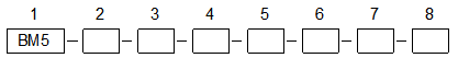
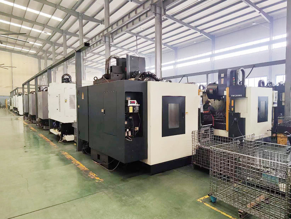
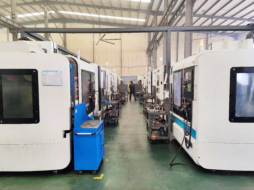
The company has focused on the field of hydraulic machinery for many years. The products mainly include: BM series orbital hydraulic motor, BZZ series and 101S series hydraulic steering control unit, FK combination valve block and other hydraulic components.
Contact Us
Address: Industrial Park of Mainland Villages and Towns, Ningjin County, Xingtai City, Hebei Province
Mailbox:miki@zs-hyd.com
Mobile:86-18333998816

Follow us