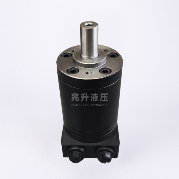
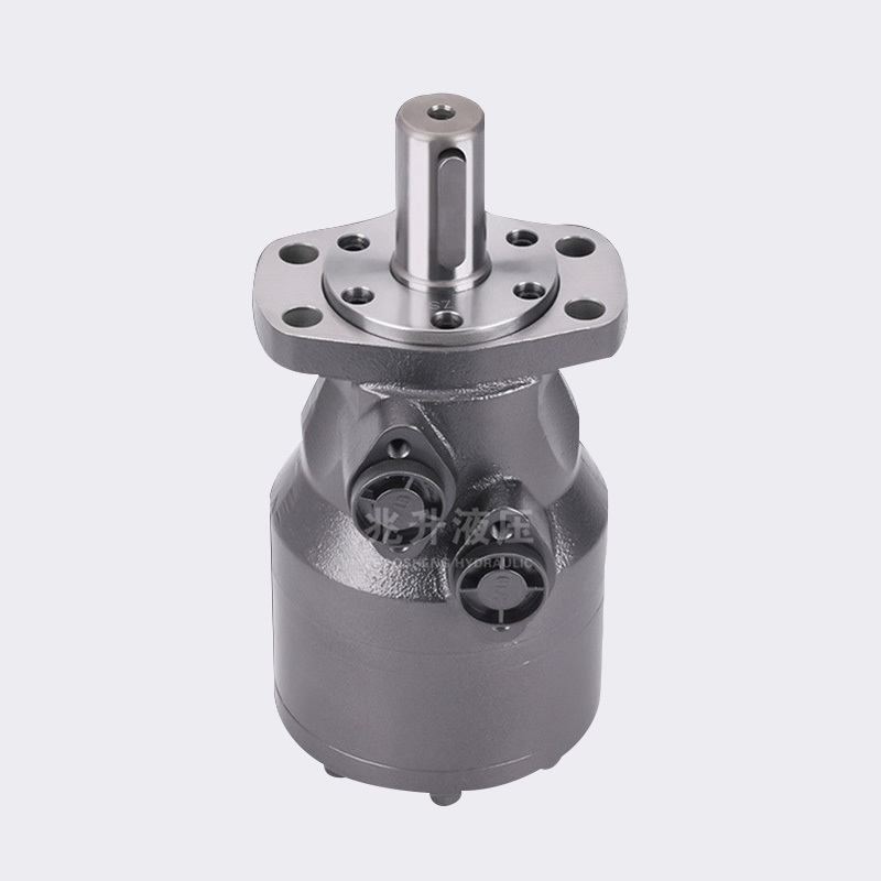
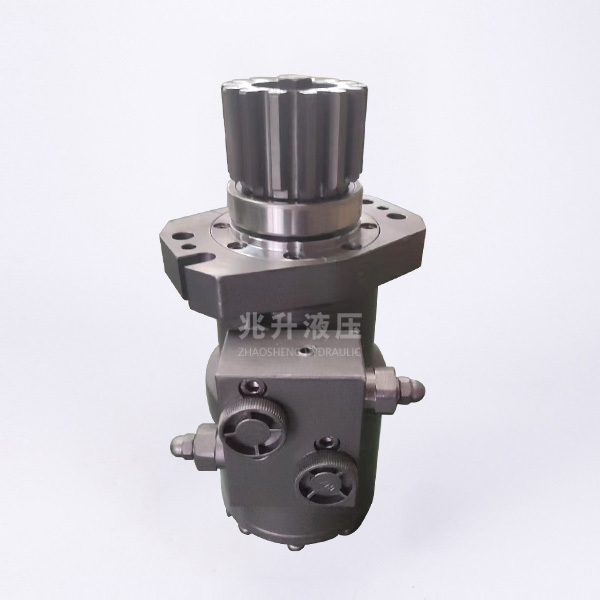
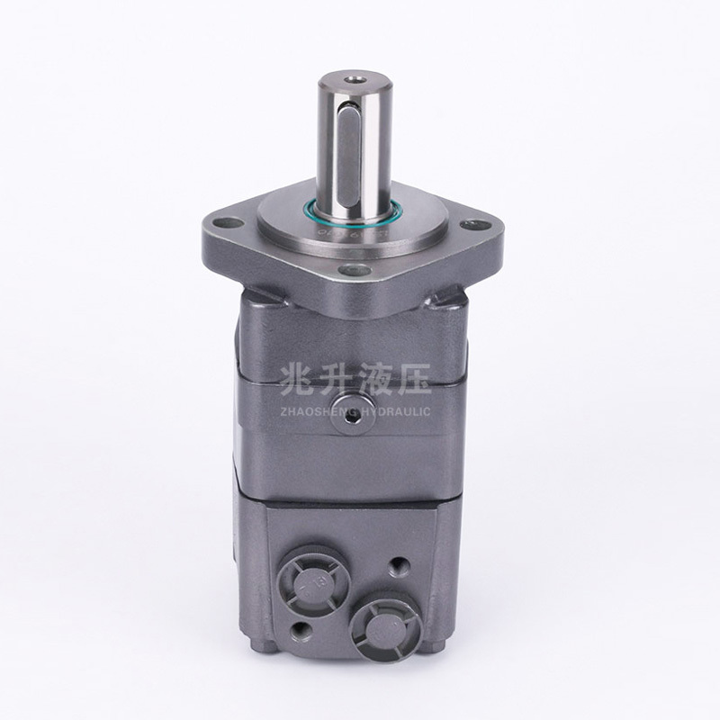
BMSY Series Orbital Hydraulic Motor
Key words:
Classification:
Description
BMSY series orbital hydraulic motor is an advanced hydraulic motor with end-face flow distribution structure. This series of motors use a column-mounted rotating stator pair, which has the characteristics of high working pressure, high working efficiency, good efficiency retention of the whole machine and long working life. On the basis of standard structure, multi-functional variant design can be carried out according to user requirements. Its characteristics:
• The use of advanced stator parameter design, low starting pressure, high efficiency and good retention.
• High working pressure and large output torque. Tapered roller bearing structure, bearing shaft, radial load capacity is strong, so that the motor can directly drive the working mechanism, the scope of use is expanded.
• Advanced end face flow distribution structure, so that the motor with high precision, wear after the automatic compensation function is strong, to ensure high volumetric efficiency, motor long life, to ensure that the motor speed is stable, smooth load speed characteristics.
• Ability to drive larger loads and higher working pressure levels.
Main technical parameters
|
Type |
BMSY 80 |
BMSY 100 |
BMSY 125 |
BMSY 160 |
BMSY 200 |
BMSY 250 |
BMSY 315 |
BMSY 400 |
BMSY 500 |
|
|
Actual displacement (cm³/rev.) |
81.8 |
100 |
121.2 |
158.8 |
200 |
254.5 |
321.2 |
400 |
497 |
|
|
Maximum speed (rpm) |
Rated |
675 |
540 |
432 |
337 |
270 |
216 |
171 |
135 |
110 |
|
Continuous |
780 |
735 |
606 |
460 |
365 |
285 |
225 |
180 |
145 |
|
|
intermittent |
970 |
895 |
735 |
560 |
445 |
350 |
277 |
220 |
180 |
|
|
Maximum torque (N.m) |
Rated |
177 |
218 |
265 |
445 |
520 |
650 |
720 |
775 |
815 |
|
Continuous |
228 |
288 |
350 |
490 |
600 |
720 |
905 |
890 |
950 |
|
|
intermittent |
309 |
387 |
465 |
600 |
725 |
900 |
1030 |
990 |
1030 |
|
|
Maximum output power (KW) |
Rated |
12 |
12.4 |
12.4 |
12.4 |
12.4 |
12.4 |
11.2 |
9.6 |
8.6 |
|
Continuous |
16 |
18 |
18 |
18.1 |
18.1 |
18 |
17 |
11 |
9 |
|
|
intermittent |
20 |
22 |
23 |
25 |
24 |
23.5 |
20.2 |
12 |
11 |
|
|
Maximum working pressure difference (MPa) |
Rated |
16 |
16 |
16 |
19 |
19 |
18 |
16 |
14 |
12 |
|
Continuous |
20.5 |
20.5 |
20.5 |
21 |
21 |
20 |
20 |
16 |
14 |
|
|
intermittent |
27.5 |
27.5 |
27.5 |
26 |
25 |
25 |
24 |
19 |
15 |
|
|
Peak |
29.5 |
29.5 |
29.5 |
28 |
27 |
27 |
26 |
21 |
17.5 |
|
|
Maximum flow (L/min) |
Continuous |
65 |
75 |
75 |
75 |
75 |
75 |
75 |
75 |
75 |
|
intermittent |
80 |
90 |
90 |
90 |
90 |
90 |
90 |
90 |
90 |
|
|
Maximum allowable oil inlet pressure (MPa) |
Rated |
21 |
21 |
21 |
21 |
21 |
21 |
21 |
21 |
21 |
|
Continuous |
25 |
25 |
25 |
25 |
25 |
25 |
25 |
25 |
25 |
|
|
intermittent |
30 |
30 |
30 |
30 |
30 |
30 |
30 |
30 |
30 |
|
* The rated speed and torque refer to the output value under the rated flow and pressure.
* Continuous value refers to the maximum value that the displacement motor can work continuously.
* The intermittent value refers to the maximum value of the displacement motor working for 6 seconds in 1 minute.
* The peak value refers to the maximum value of the displacement motor working for 0.6 seconds in 1 minute.
Ordering Information

|
POS.1 |
2 |
3 |
4 |
5 |
6 |
7 |
8 |
||||||
|
Structure Code |
Displacement |
Flange, stop |
shaft extension |
Oil port |
Rotate Working condition |
Paint Options |
Special Function |
||||||
|
BMS |
80 |
E2 |
2-φ13.5, diamond flange, stop φ82.5X6.3 |
A |
Straight axis φ25, length 41.8, flat key 8X7X32,M8 |
D |
G1/2,G1/4,2-M10 |
None |
Standard |
00 |
No paint |
None |
General |
|
100 |
E4 |
4-φ13.5, square flange, stop φ82.5X6.3 |
B |
Straight axis φ32, length 56, flat key 10X8X45,M8 |
M |
M22X1.5,M14X1.5,2-M10 |
R |
Reverse |
None |
blue paint |
|
|
|
|
125 |
EB4 |
4-M14, indexing circle φ108, square flange, stop φ82.5X6.3 |
D |
Straight axis φ25.4, length 41.8, flat key 6.35X6.35X25.4,1/4-20UNC |
S |
7/8-14UNF 'O'-ring,7/16-20UNF 'O'-ring,2-3/8-16UNC |
|
|
B |
Black paint |
|
|
|
|
160 |
E6 |
4-φ13.5, diamond flange, stop φ82.5X6.3 |
F |
Involute spline shaft φ31.75, length 48,14-DP12/24,3/8-16UNC |
S1 |
7/8-14UNF 'O'-ring,7/16-20UNF 'O'-ring,2-M10 |
|
|
S |
silver gray paint |
|
|
|
|
200 |
F6 |
6-φ13.5, diamond flange, stop φ82.5X2.8 |
FD |
Involute spline shaft φ31.75, length 56.2,14-DP12/24,M8 |
P |
1/2-14NPT,7/16-20UNF 'O'-ring,2-3/8-16UNC |
|
|
|
|
|
|
|
|
250 |
W |
4-φ13.5, wheel flange φ160, stop φ125X8 |
K |
Straight shaft φ25.4, length 41.8, semicircular key φ25.4X6.35,1/4-20UNC |
|
|
|
|
|
|
|
|
|
|
315 |
B2 |
4-φ13, square flange φ127.7, stop φ100X6 |
S1 |
Rectangular spline shaft 6-25.32X21.47X6.25, length 41.8,1/4-20UNC |
DB |
G1/2,G1/4 |
|
|
|
|
|
|
|
|
400 |
|
|
I |
Involute spline shaft φ22, length 33,13-DP16/32 |
DU |
G1/2,7/16-20UNF 'O'-ring |
|
|
|
|
|
|
|
|
500 |
|
|
G |
Straight axis φ31.75, length 48, flat key 7.96X7.96X31.75,3/8-16UNC |
SB |
7/8-14UNF 'O'-ring,G1/4 |
|
|
|
|
|
|
|
|
|
|
|
SL |
Rectangular spline shaft 6-34.85X28.14X8.64, long 100,M8 |
WATER |
7/8-14UNF 'O'-ring,7/16-20UNF 'O'-ring |
|
|
|
|
|
|
|
|
|
|
|
P |
Straight axis φ30, length 48, flat key 10X8X40,M8 |
M4 |
M22X1.5,M14X1.5 |
|
|
|
|
|
|
|
|
|
|
|
J |
Rectangular spline shaft 6-30X25.3X8, length 48,M8 |
PB |
1/2-14NPT,G1/4 |
|
|
|
|
|
|
|
|
|
|
|
N |
Rectangular spline shaft 6-30X24.8X6, length 48,M8 |
PU |
1/2-14NPT,7/16-20UNF 'O'-ring |
|
|
|
|
|
|
|
|
|
|
|
Z |
Rectangular spline shaft 6-32X26X6, long 56.5,M8 |
|
|
|
|
|
|
|
|
|
|
|
|
|
|
|
G2 |
G1/2,M10X1 |
|
|
|
|
|
|
|
|
|
|
|
|
|
M3 |
M22X1.5,M10X1 |
|
|
|
|
|
|
|
|
|
|
|
|
|
S1 |
7/8-14UNF 'O'-ring,M10X1 |
|
|
|
|
|
|
|
Note: When using the ordering information, the user can write the motor structure, displacement, mounting flange, shaft extension, oil inlet and outlet and other information to us according to the above format by selecting the code of the colored part on the left. If the selected specifications are not in the above table or special requirements, please contact us.
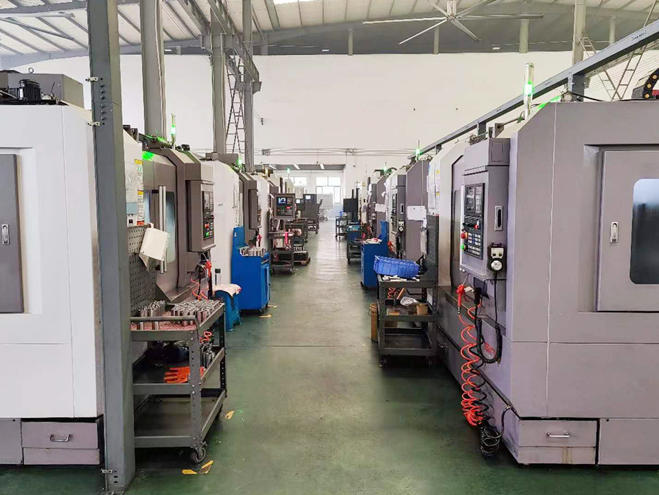
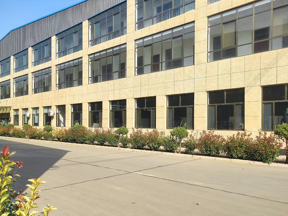
Factory
Previous:
The next one:
Inquiry


